The Flexible Rocker Telescope
Okay, it is high time I made good on my threat to make a webpage about the Flex Rocker Telescope. So here it is.
In 1997 I designed and built a new 22" telescope. When I had the tube assembly pretty much built and figured out, I turned to thinking about how did I want to build the rocker box? I was doing this thinking one summer day on Mt Pinos, in southern California, while sitting in a chair and staring at a field of telescopes.
I had already considered equatorial mounts and equatorial platforms when I had my 17.5" telescope, and so I had already decided that I like the altitude-azimuth mount. I did not want to build a Dobsonian, because I have met John Dobson many times and I have found him to be an obnoxious person. I have witnessed him being rude not just to me personally, on a few occasions, but to hundreds of people at once on two other occasions. This was simply because he is selfish and greedy.
Also, as I was contemplating the rocker box, two other things came to mind. First, while I was lost in thoughtland, I was slow in recognizing the roaring noise behind me. So it took me by surprise when I got ran over by a big dust devil. As this thing swept across the observing field it toppled telescopes, tables, chairs, etc etc. Looking up into the middle of it I saw papers and plastic bags being sucked up thousands of feet into the sky.
Watching these telescopes hit the ground made me aware of just how unstable a "Dobsonian" mount really is. The Dob mount rocker box has four points/pads on top to support the OTA, and it has three points/pads on the bottom where it contacts the ground board. This arrangement means the force has to travel around a right angle corner as the weight is transferred through the rocker box. As a result the bottom has a lot of bending pressure on it. So the rocker box has to be very stiff and heavy to handle the load. It is structurally unsound.
Furthermore, if you turn the box upside down and look at the three support pads, you will see that they describe a triangle. This triangle has sides which pass fairly close to the center pivot bolt. The distance from the side of the triangle to the azimuth bolt is usually less than half of the diameter of the primary mirror. So that the edge of the primary mirror usually hangs over the side of the structure which is supporting it. Having a heavy mirror over a narrow support structure means that the whole thing is easy to topple in a wind or earthquake. Not good!
The second impact came when I realized this, my favorite observing location, is perched right on top of the San Andreas Fault line. This is actually the location of the 'Fort Tejon Earthquake', the most powerful earthquake ever recorded in California. These three reasons caused me to contemplate whether I could re-design the rocker box.
What I wanted was a wider base of support under the mirror, and a more structurally sound rocker box. I realized that here we have a big square box, yet on the bottom we have three points of support forming a triangle which is much smaller than the box. Right away it was obvious that I wanted four points on the bottom, and those four points at the corners of the box.
So I removed the three points from the top of the Dob groundboard and placed four points on the bottom of the rocker, at its corners. Having the four altitude support pads on the top of the box directly over the four azimuth support pads on the bottom corners of the box means that the force goes directly thru solid material (the side of the rocker box). It cannot collapse. A Dob box has the force going around a right angle corner, such that it can collapse easily. Also, those four points on the bottom of the rocker now describe a rectangle which is very much larger than Dobson's triangle, so that the base of support under the mirror is now much wider. It is larger than the mirror, so it will do a much better job of resisting wind and earthquakes.
The flexible rocker has four altitude bearings and four azimuth bearings. The "problem" with this arrangement is that the four points are not likely to be in a perfect plane, no matter how well you build it. And the ground board is not likely to be perfectly flat, no matter how well you build it. This means that three of the points on the rocker will describe a plane matching the shape of the groundboard. So the telescope will rock back and forth on the high points.
But that is assuming you have a stiff rocker box. The answer was to build a flexible rocker box! That way the weight of the Optical Tube Assembly on its four pads will bend the bottom of the rocker box so that all four bottom pads contact the ground board at all times. As the scope is rotated in azimuth the rocker box will bend back-and-forth as it goes over the non-flat ground board. That way all four top pads will always contact the OTA and all four bottom pads will always contact the ground board. My solution was to make the rocker flexible in the "twisting" direction. It is stiff side to side to keep from falling over, but the two side panels (with the altitude and azimuth bearings) can rotate a little bit relative to each other. This always keeps all four azimuth pads on the ground, even when the ground is not perfectly flat.
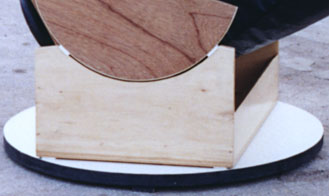
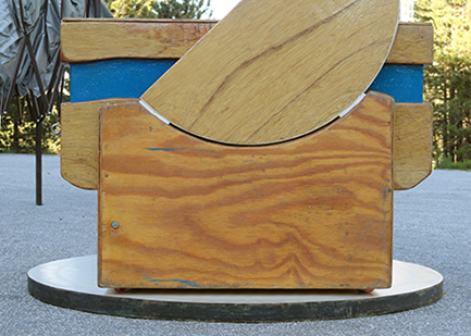
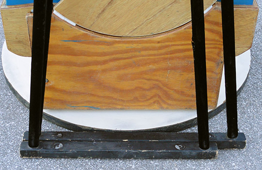
Below you will see a picture of the flex rocker as it was first constructed. You can plainly see that the altitude pads transmit their weight through solid material (three-quarter-inch plywood) to the azimuth pads below them. The perceptive among you will also recognise that my rocker is actually a rectangle. I did this because I had small altitude bearings, and I wanted to minimize the size of the ground ring. I knew that I could make the rocker shorter and even more stable if I used larger altitude bearings. But I already had the round, good-looking piece of plywood which I had cut out of the front of the mirror box, and I wanted to use it (and I didn't want to buy more plywood). Besides, I still didn't know if the flexible rocker would work out.
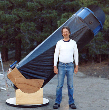
I used cheaper wood for the rocker and ground board since I had never heard of the concept, and was afraid I'd have to throw them away and build a "real" Dob. The images below show the finished Flexible Rocker:
My method of keeping the mirror box centered inside the rocker box was to put one-inch-wide Teflon altitude pads on the three-quarter-inch sides of the rocker box, such that the pads are even with the outside and hang over the inside a quarter-inch. The quarter-inch overhang rides against the sides of the mirror box and keeps it from rubbing the rocker box.
Looking at the rocker from the side, the "twisting" flexibility would move the side panel in a clockwise or counter-clockwise direction. Picture the bottom panel of the rocker having four corners - two opposite corners go up while the other two opposite corners go down as the rocker is flexed. Yet the rocker is stiff in the direction which holds the two side panels vertical - otherwise it would collapse (each side panel holds two altitude pads and two azimuth pads).
Another way to look at it is this: Dob mounts have three feet on the bottom of the ground board for stability on uneven ground. They have four altitude bearings on the top of the rocker box to support the weight of the tube. Somewhere in between has to be a piece that is stiff enough to convert the four points of weight into three points of support. Usually it is the rocker box. Many of you have seen very flimsy looking groundboards under a stiff rocker box. The three azimuth pads are directly over the feet, so the force is transmitted directly from the pads to the feet. But if the stiffness is built into the groundboard, then the rocker box can be built very flimsy.
All that is really required is that you have four azimuth pads, each right under an altitude pad, and a means to hold them there. The force on each altitude pad is transmitted directly to the azimuth pad below, preferably through solid material. In my case, you can see that each side panel of the rocker has two pads on top and two on the bottom. One 3/4" plywood panel supports half the tube. Of course, even the stiff groundboard will flex a bit, and it is not perfectly flat anyway. So as the telescope moves in azimuth, the rocker has to bend to keep all four pads on the groundboard, and at the same time keeping all four altitude pads in contact with the altitude bearings. If you can picture one azimuth pad out of four hitting a hole and dropping a bit, now the two side panels are not parallel. One side has twisted, putting a torque on the rocker, and flexing it. The two side panels do most of the work, the rest of the rocker structure just has to keep the two sides vertical as seen from the front or back (it would be embarassing to have your telescope come crashing down).
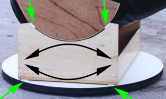
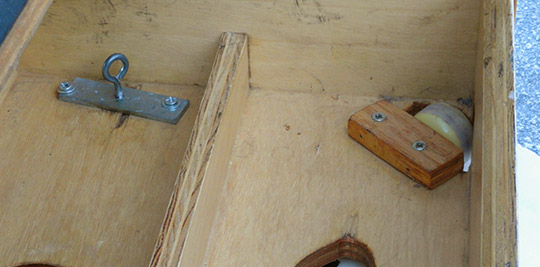
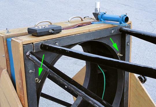
The image below has four green arrows - two pointing to the Teflon altitude pads and the other two pointing to the Teflon azimuth pads below them. The two black arrows demonstrate the "twisting" motion the sides of the rocker box undergo as the scope is moved in azimuth:
Now, when it comes to the ground board, it is obvious that the flat, paved, parking lot suffices if your four azimuth pads are replaced with wheels at a 45-degree angle. No board was needed. If you're setting up on a sidewalk, there is no need for the three feet. You can use the hard, smooth and level surface as the rigid ground board, and all you provide is the top surface if you need one. This allows you to have a flex rocker and no groundboard at the same time. But I required the use of Digital Setting Circles, and they require a connection to the ground so that rotation around the central pivot can be measured (the azimuth motion). My ground board was in the shape of a ring upon which the four rocker box azimuth pads run, with a connection to the center to hold a pivot bolt for the DSC. The Dob ground board is usually in the shape of a small triangle, and the three pads are mounted on the ground board instead of on the bottom of the rocker box. The ground ring under a flex rocker is much larger, because it provides a much wider base of support for the telescope.
I showed this arrangement to the public at RTMC in May, 1998. As soon as I began setting it up it was obvious to Tom Clark, who was there talking to me, that this was something different. So he took a picture of it, and you can see that picture in the Fall 1998 issue of Amateur Astronomy Magazine, in the article he wrote about the 1998 RTMC. And during the event several dozens of folks came to ask me about it. It was obviously something new, and they wanted to know what is was and how it worked. Many of them asked me "what do I call it"? Something which never existed before needs a name by which it can be referred to. I didn't have an answer, so I merely told them it was a "flexible rocker". That name stuck.
The world's second flex rocker was made by Dan Gray. His webpage used to say he and his friend invented the concept in 2000, but later he changed that to say he built it in 1998 (apparently an attempt to claim he invented it?). Either way, he is the person who shortened my "flexible rocker" term into "flex rocker" (perhaps indicating that he talked to me at the 1998 RTMC and got the name there). Flex is short for flexible, which is the opposite of a stiff Dob rocker. Also, he used a larger altitude bearing to shorten the box. And he did not need a DSC, so he put wheels on the bottom and used it without a ground ring when he had a nice sidewalk.
Nowadays many people are using the huge altitude bearings in order to shorten their rocker boxes. But simply having a short rocker does not mean that it is a flex rocker. A flex rocker has four points on top, and four corresponding points on the bottom. Each top point conducts force 'directly' thru solid material to the point below it. Of course, it is not possible to make the ground board nor the bottom of the rocker perfectly flat. So with a stiff rocker the thing would rock back and forth on the two highest points. Therefore, I designed and made my rocker flexible! It bends to the point where all eight points contact at all times. It is relatively light-weight. Flex rockers are now being made around the world, from the USA to France to Australia.
www.bbastrodesigns.com/osp2003/OSP2003.html
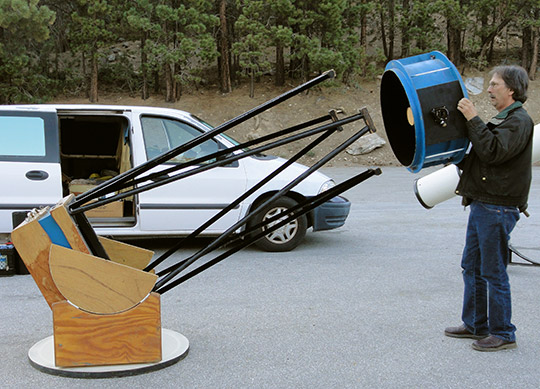
On the atmlist, Dave Smith said: "It is a very elegant solution!" And Mel Bartels said: "Exactly! The 'weakness' of the flex rocker is turned into its strength - namely that the bearings maintain solid contact at all times."These pictures show the current state of that original flexible-rocker telescope. It turned out that my 22" F/4.5 Galaxy Optics mirror was very poor, even after they refigured it. So I aquired a used 22" F/4.6 mirror, which turns out to make excellent images. Not only does this mirror have a longer focal length, it is also a quarter-inch thinner. These two things changed the balance point of the tube quite a bit. So I had to cut open my mirror box and lengthen it - this was to increase the distance between the mirror and the balance point. Simply using longer poles would not have changed the balance in the proper place. You can see the extension which is the part I painted blue (yes, the scope has been banged up over the years, as I use it a lot - but I don't worry about such things):
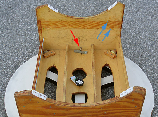
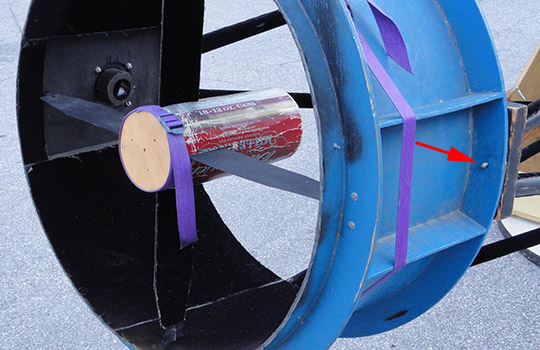
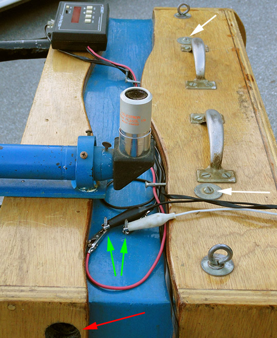
As a result I also had to cut the flex rocker in half and increase its height. At the time I took the opportunity to remove the four Teflon azimuth pads from the bottom and replace them with wheels. I now have a carpet pad mounted under it to provide friction, which is controlled by a bolt. That way the bolt can be tightened to vary the friction in azimuth - and at the same time the carpet pad keeps the track clean. The next pictures show the inside of the flex rocker, including the azimuth encoder. A red arrow shows the bolt I turn to vary the azimuth motion by placing more of the telescope's weight on the carpet pad. The blue arrows indicate how much I had to extend the height of the rocker:
The four azimuth bearings were originally teflon on FRP (fiber-glass reinforced plastic), but are now made of skateboard wheels, which work better. Since the bearings are farther from the azimuth pin than on a Dob, they have more leverage, and so made the scope harder to turn. Teflon on FRP is supposed to be slipperier than on Ebony Star, but there is a limit to how far you can go. Also, since the azimuth bearings face down, they tended to pick up dirt. The wheels roll right over bugs and grit. A carpet pad and a bolt provide variable friction of the azimuth motion, and also clean the track at the same time.
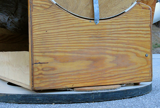
The wheels are slightly inboard of the corners, and that means that the force is no longer transmitted completely through solid material. One side of each axle is under the corner, but the other end is inside, under the strengthening blocks. In the next picture you can see the wheels under the corners. You can also see the carpet pad which cleans the track and provides friction for the azimuth motion. The metal strap at the top holds the altitude encoder for the digital setting circles:
Other innovations
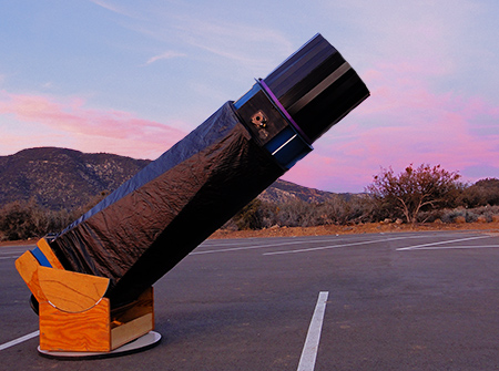
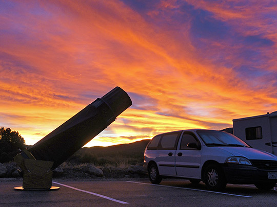
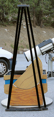 on this 22" F/4.6 Newtonian telescope include the truss assembly. Consider a truss telescope while it is pointed 45 degrees up from the horizon (like in the picture at the top of this page). The four altitude poles (on the sides) are currently supporting the entire weight of the upper cage against gravity. The four (top and bottom) azimuth poles only prevent the cage from twisting out of position, and they support the altitude poles in a sideways fashion, including when you move the scope in azimuth. So the altitude poles have a much higher load, therefore they need to be stronger.
I wanted to design my truss structure as four triangles, based on a metal scope made many years previously by Dick Nelson. (By coincidence I saw my first StarMaster telescope late that summer of 1997, and found out he also makes triangles very similar to mine.) So what I did was to make the two altitude triangles (left and right sides) take up the maximum amount of space, and the two azimuth triangles (top and bottom) took up whatever space was left over. That way the altitude triangles have a wider base, which gives them more strength. I also drilled holes in the azimuth triangles to lighten them. Each triangle has a bolt protruding from the top, and the upper cage has four coresponding holes. This makes it very easy to install the upper cage - I just drop the holes over the bolts, then when everything is under control I can install the wing nuts on the bolts.
The picture below shows the cage partially installed. The top wingnut has been tightened, that and gravity holds the cage onto the scope. Then I can go around at leisure to install the other three wingnuts. The red arrow points to the bolt on the top of the left triangle protruding through the hole in the upper cage, and waiting for a wingnut. The picture also shows the secondary mirror cover I made from a Budweiser box and a piece of wood. This allows me to cover and protect the mirror without ever touching it. Indeed, that mirror is washed only once every few years. You can also see the focuser baffle, which has velvet on the side facing the eyepiece. The inside of the upper cage and the inside of the poles are also covered in velvet, as does the vertical spider vane:
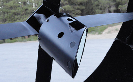
The secondary mirror holder is made out of anodised aluminum flashing. It has holes to allow the mirror to cool off as rapidly as possible:
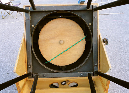
In the next picture you can see that the altitude triangles have a wider base, and the wing nuts which hold them onto the mirror box. You can also see the tight-fitting primary-mirror cover and both of the digital setting circle encoders. The gold knobs are for collimating the primary mirror. Having the two different length poles causes a difference in the vibrational frequency, thereby helping the assembly as a whole to dampen quicker. I should have made the azimuth triangles using a smaller diameter tubing. The poles are covered in black velvet:
Another feature which I have never seen is my method of installing and uninstalling the secondary cage. I have watched (sometimes in horror, sometimes in amusement) as owners of large Dobs carry their upper cages up to the top of their ladders, and then precariously lean out over their primary mirrors to install the cage. This involves a dangerous and very clumsy procedure trying to get the poles aligned and in contact with the cage. I swore I would not do this, and decided I want to be standing on the ground when I install my cage.
Having my eight poles pre-created as four triangles gives them the stiffness and strength to accomplish my goal. It also means that I only have four points of contact to deal with, instead of eight; and all of those points are in easy reaching distance. The mirror box has eight studs protruding from it, I install the triangles by dropping them onto the studs and securing them with wing nuts. Then I prop up the back of the mirror box with a perfectly-sized piece of wood. Now I can safely and easily install the upper cage while standing on the ground, as seen in this next image. I can uninstall it by reversing the steps:
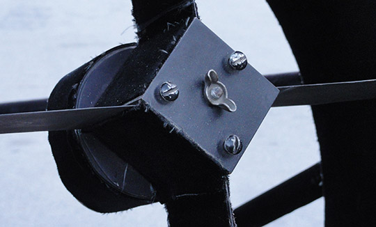
Another unusual feature is that the primary mirror is collimated from the front of the telescope. Literally, the primary mirror cell hangs from the front of the mirror box. The bottom of the three collimation points is permanently fixed on a universal-joint. This U-joint prevents the mirror from creeping up and down the tube. So I end up with only two collimation knobs, both on the top front of the mirror box. I also made an extension pole so that I could adjust them while looking into the Cheshire eyepiece.
Also from that diagram you will notice that the height of the sling is adjusted from outside the mirror box [note that only part of the sling is shown, for clarity, and the 18-point support is not shown]. Indeed, the mirror's lateral support hangs from the top of the box, supported on the inside by an aluminum angle. Also attached to this angle are the two handles by which I carry the mirror box. That way when I carry the box the weight of the mirror is not supported by the box itself, it hangs from the handles. And when the mirror box is loaded into the transport vehicle, the strength of the sling protects the mirror from flying forward during braking. The next image shows the primary mirror's collimating knobs:
This next image shows how the handles and the sling adjustment bolts are in line with the eye-bolts holding the aluminum angle. The white arrows point to the sling adjustment bolts, the red arrow points to the ventilation hole in the side of the mirror box (the fan is inside), and the green arrows point to the power contacts. The black and white leads bring electricity from the battery to the posts. The Lumicon Sky Vector digital setting circles take power from there with leads, but the two fans are wired internally to the posts. You can also see my fancy-schmancy one-inch single-element finder scope [yes, I have bigger scopes I could mount here, but it only has to find Jupiter, Saturn, Luna, and my two alignment stars]:
Another real nice feature is the secondary mirror collimation. I can collimate it without tools while looking in the sight tube. The center post is spring loaded, so that when I turn one of the three collimation knobs the mirror moves right away. There is no need to loosen one and tighten another. A wingnut on the center bolt snugs it down so the mirror does not rotate during transport. The four-vane spider is made of two pieces of steel, each bent into an "L" shape, using a pair of 45-degree bends inside the collimation box:
The mirror box has six sides for strength. The back is completely baffled to prevent light trespass, but also open to allow air in for cooling. The front serves five purposes: First, the side greatly stiffens the box, and this design requires a stiff mirror box. Second, it provides a surface upon which to mount the truss poles. Third, it is the surface from which the mirror cell hangs. Fourth, it has a round hole which is a light baffle. And fifth, it is a wind baffle, as I explained on the atmlist many years ago. The purpose of a fan is to cool the mirror, so that there is no boundary layer on the front. So if you have a 'strong' fan blowing on the back of the mirror, and the tube is pretty well closed up, the air from the fan will hit the back of the mirror and go around the edge of the mirror and up the tube. But if there is a baffle just inches above the mirror, the air will hit it and be forced back down into the front of the mirror. This serves the added purpose of removing the boundary layer while it helps to cool the front of the mirror as well as cooling the back of the mirror. So the single fan becomes more efficient.
I have a full shroud and a full light-shield/dew-shield, as seen in the picture at the top of this webpage. The rule-of-thumb for Newtonians is that the tube should extend above the focuser a distance equal to the diameter of the tube. This is for light and dew rejection. My shield prevents light reaching the eyepiece even when cars are driving around with headlights on. And it really paid off big the night all the other Newtonian secondary mirrors frosted over - I was the only telescope still observing (the refractors and SCTs had gone to bed long before). The light/dew shield is made of corrugated plastic sign-board and lined with velvet.
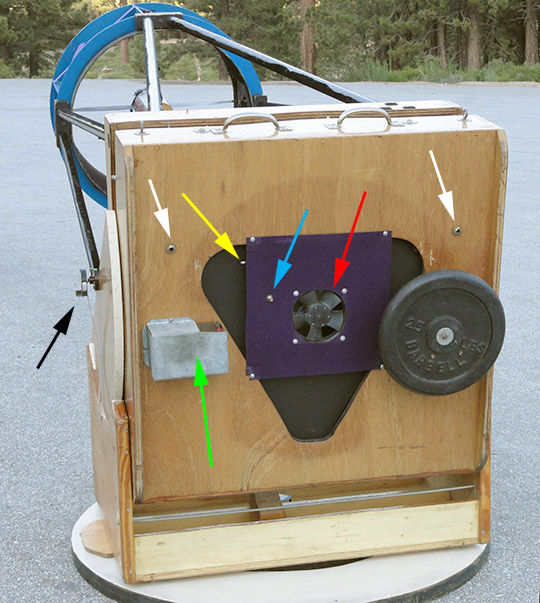
I have a strong 110cfpm 12-volt 0.7-amp fan, which is mounted on felt to dampen vibrations, blowing on the back of the mirror (the red arrow in the picture above). I also have an internal exhaust fan to suck the warm air out of the top of the mirror box. I have a third fan which blows onto the front of the mirror to clean off the boundary layer when the mirror is warm, but this fan is rarely needed and rarely installed. The seven-amp-hour 12-volt gel-cell battery is mounted to the back of the scope (in a steel enclosure, green arrow). The black arrow shows the altitude encoder. At the bottom-left of the image you can see the board to which the carpet pad is mounted. The white arrows show the collimation bolts as they protrude through the back of the mirror box. The yellow arrow points to the ON-OFF-ON switch which controls the two fans (the big one on the back and the little ventilation fan inside the top of the mirror box). I can turn either fan on, or both off, but I can't turn them both on at once. Should I choose to install the fan blowing on the front of the mirror, I can turn that on separately. The blue arrow points to the potentiometer which controls the speed of the two permanent fans. The black triangle is actually the primary mirror's cell, seen through a triangular hole in the mirror box. Air can get in all around this triangle, and also through a big hole in the center (hidden by the fan).
Finally, yes, I do know how to balance a telescope. The reason I chose to put a weight on the back is because I had to store the scope in a small room accessible only through a narrow door. That door ruled out the use of 'wheelbarrow handles' and dictated that I move the scope around upright, on a dolly I made (it looks like a big skateboard). So in storage the mirror rests on its sling, which by now is fully stretched out. The narrow doorway required that either I make the altitude bearings removable, or I mount them very close to the mirror. I chose the "close to the mirror" with a bad center of gravity since I already had the small bearings, and I wanted them permanently attached. If I was making the bearings from scratch, I would have made them with a larger diameter, and removeable, and at the center of gravity.
Thank you's to my friends Les Saunders, Ed Grissom, and Robert Burns, who helped me make this scope.
Happy atm'ing!
Copyright © 1998 - 2011 by John Sherman
HOME EMAIL