|
|
Astigmatism
|
A telescope is stigmatic if it produces a round, pinpoint image of a star. If the image is not round the telescope is astigmatic. Glass optical elements have a curve polished into them which bends and focuses the light, to make an image. The curve is normally supposed to be a figure of revolution around an axis. Usually it's a sphere or parabola with the axis of revolution in the physical center of the glass (although I will describe the spot tests in relation to telescope mirrors, the discussion also applies to refractive lenses and other optical equipment). Normally, the optical axis is the line starting at the center of the mirror and proceeding out perpendicular to the surface of the mirror, to the eyepiece. If the mirror is "round" you can rotate it around the optical axis and every position is the same. This will produce a stigmatic image. But if there is any out-of-roundness in the rotation it will produce an astigmatic image. The big advantage of the spot over the straight edge is that the spot sees astigmatism directly, whereas the straight edge can only detect part of it. The straight edge shows you the fact that there is a problem. If you rotate the device to many different orientations you can build up enough information to determine the extent of the problem. Astigmatism is a defect which occurs in two dimensions, and a straight edge sees only one dimension at a time. Spot testing works in every dimension at the same time, and so it will automatically see the two-dimensional aberration in its entirety. It doesn't need to be rotated to learn the parameters of the problem. For example, set up a mirror on a test stand and illuminate it with a pinhole. From your perspective behind the roc, the mirror appears flat. You can not see the three dimensional aspect of the mirror, so it appears to you in two dimensions only. Now hold a Ronchi grating in the light path, so that several vertical lines are showing. Now move the grating from left to right, you can plainly see it move. You can make measurements and calculations in the horizontal direction. Now move the grating up and down. You can not see any movement, and you can not make any measurements. Now move the grating in a diagonal direction. You can plainly see the horizontal part of the movement, but you know nothing of the vertical movement. All of this is because the Ronchi grating works in only one dimension out of the two which you can perceive. When the lines are vertical, you can use the horizontal dimension/diameter. This is fine if your mirror does not have astigmatism. If your mirror is round (rotationally symmetric about its optical axis) you can make a measurement across any diameter and they'll all be the same. Astigmatism happens when you can measure across different diameters and get different results. Now replace the grating with a spot grid. You can plainly see it move in every direction because it works in two dimensions. The spot has an edge pointing in every direction, thus it will automatically see and show astigmatism. You instantly see the orientation, shape and degree of the aberration.
|
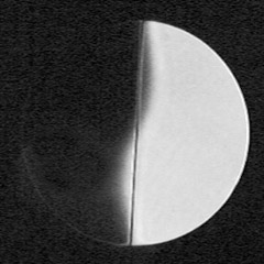
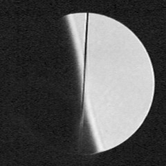
On the left above is an image showing a knife edge occulting most of
the mirror outside the roc (radius of curvature). On the right
is an image showing the knife at the roc, and the mirror is nulled.
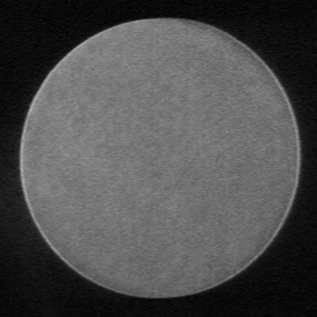
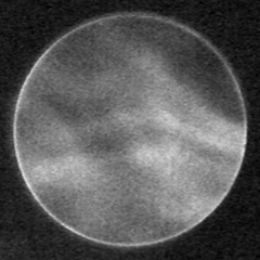
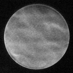
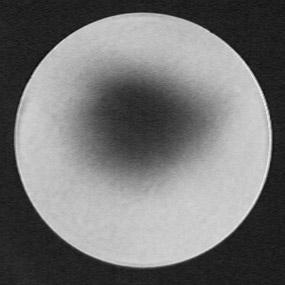
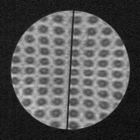
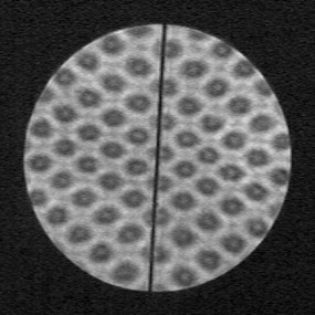
 The two images above show a 150 lpi Ronchi grating outside the roc. The third image to the left shows the same Ronchi grating inside roc. Even with the large pinhole, the Ronchi grating displays nasty amounts of diffraction interference effects. Next we get to see an image made with one of my custom-made spot grids inside the roc (below, right). Notice that the rows and columns of spots are in straight lines. As with the Ronchi grating, a spherical mirror does not distort the apparent positions of the spots. They appear the same as they do on the grid. Diffraction causes the dark shadows of the spots to have a bright spot in the center. Diffraction also causes dark lines to appear between the spots. 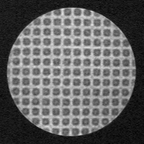 The next image shows my 7" spheroid nulled with a 0.005" spot (below, left). Since the spot is the same size as the image of the pinhole which is formed by the mirror, the image goes almost dark. Mostly you just see a bright rim around the mirror, which is a diffraction effect. This shows that there is no significant astigmatism in the mirror. A smaller spot and a smaller light source would produce an even more sensitive result, but would be too dim for my camera to record. 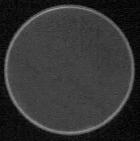 In case you're wondering how sensitive this null is, there are three pictures below showing turbulence. While I had the mirror nulled with the spot, I walked between the mirror and the camera. The turbulence thus created ruined the null. When the air settled down the null returned. These are just pressure gradients, there are no heat waves here. It appears to me that the spot test null is just as sensitive as a knife-edge null, with the added benefit of working in two dimensions. |
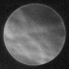
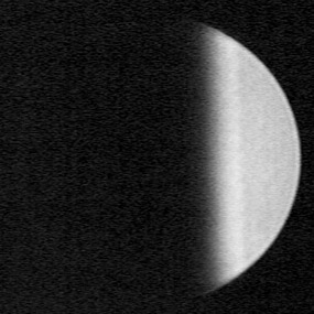
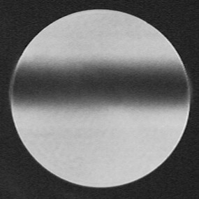
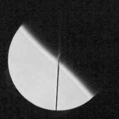
 Now we can get into it. Here I will create astigmatism by moving the light source three inches from the optical axis, which gives six inches lateral separation between the source and its image. Now when I bring the same spot into the roc, the astigmatism prevents it from nulling the mirror. All that happens is that the shape of the spot's shadow is distorted. For this image the spot is slightly above center. Now we can get into it. Here I will create astigmatism by moving the light source three inches from the optical axis, which gives six inches lateral separation between the source and its image. Now when I bring the same spot into the roc, the astigmatism prevents it from nulling the mirror. All that happens is that the shape of the spot's shadow is distorted. For this image the spot is slightly above center. The images below show what you see when the spot is inside (below, left) and outside (below, right) the average roc of the astigmatic image. Instead of seeing a round shadow, the shadow is stretched into a bar. This bar tells us the orientation of the short roc of the astigmatism, and the long roc. You can see that the spot itself is still slightly above center. |
|
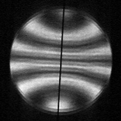
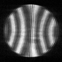
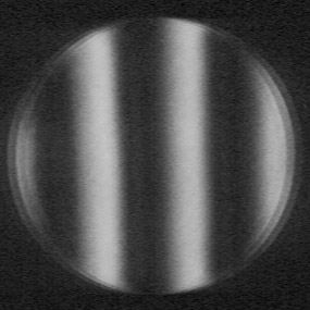
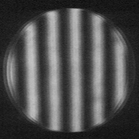
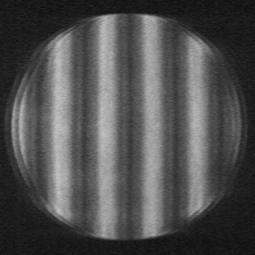
A Ronchi grating behaves the same way as the knife edge does. The next two pictures show a 150 lpi grating inside the roc. The left picture has the grating horizontal, aligned with one of the astigmatism axes. The right-hand picture shows the grating aligned with the vertical axis. You might notice that the Ronchi grating is easily fooled by the astigmatism. You cannot tell from either one of the photos whether it is an otherwise spherical mirror with astigmatism, or if it is a paraboloid mirror without astigmatism. Only when the Ronchi grating is turned at a 45 degree angle to the astigmatism axes 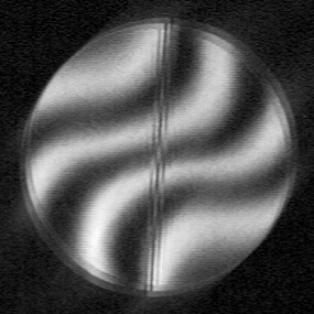 does it display the curved lines which betray the correct aberration (left). does it display the curved lines which betray the correct aberration (left).A spot grid does not have the same problems. Below are two photos of my Spot Grid inside the roc. I am using a Spot Grid with very straight and even horizontal and vertical rows and columns of spots, as seen above. Each spot is 1/200" diameter. The picture on the right is actually closer to the roc, which is why there are fewer spots showing. In both cases the spot grid immediately betrays the astigmatism, and it's orientation. Notice that there are more spots vertically than horizontally. By counting the spots in the picture, and knowing the other dimensions of the test setup, you could calculate exactly the amount of astigmatism I have imposed into the mirror. | ||
  | ||
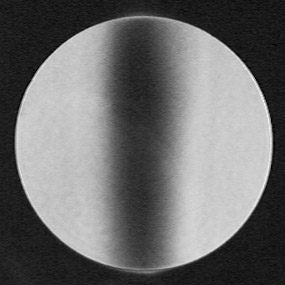
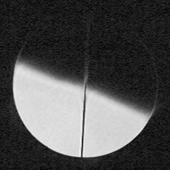
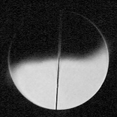
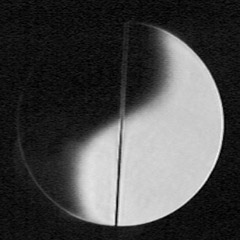
 Rotating the spot grid 45 degrees doesn't change anything (right). You can still immediately see the astigmatism and its orientation, and you can still calculate its severity from a single photo. A spot grid works in two dimensions. Next is the image of a single spot just inside the roc (below, left). This is the same 0.005" spot I used for the similar set of photos near the top of this page. Notice that the shadow of the spot has been drawn out into a bar, as before. This bar is exactly oriented with the short roc of the two astigmatism axes. Because the bar is thinner you can tell there is more astigmatism in this set of photos than the other set, when I used a lateral separation to achieve the aberration. 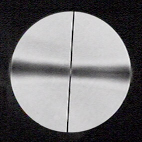 The next photo has the spot right at the roc (below, right). Once again, the shadow of the spot does not null the entire mirror. Remember, at the top of the page there is a photo where this same spot nulls (darkens) the entire mirror while in its spherical state. 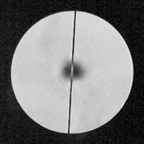 Next the spot is just outside the roc, and once again it's shadow is drawn out into a bar exactly oriented to the long roc (below, left). But this time you can see that the bar has a different structure. In the center is a relatively dark spot, which is the out-of-focus image of the spot. The rest of the bar is darkest at the ends (and rounded off), and fades towards the center. This is because of the manner which I used to impose the astigmatism into the mirror. When I used the lateral separation it affects the whole mirror more evenly. But you can see that now I'm usi 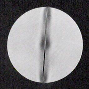 ng a wire
across the face of the mirror, and it only touches the top and bottom
edges. So the astigmatism is more pronounced at the top and bottom. This
is a level of detail you will not see from a straight-edge testing device.
Notice on the horizontal bar (two pictures up from here), that the bar is
narrower in the center? That is because the bar is pushed on by a single
bolt in its center. Where the bolt pushes there is more pressure, towards
the ends the bar bends and there is less pressure. This demonstrates the
difference between seeing astigmatism, or only detecting
it. ng a wire
across the face of the mirror, and it only touches the top and bottom
edges. So the astigmatism is more pronounced at the top and bottom. This
is a level of detail you will not see from a straight-edge testing device.
Notice on the horizontal bar (two pictures up from here), that the bar is
narrower in the center? That is because the bar is pushed on by a single
bolt in its center. Where the bolt pushes there is more pressure, towards
the ends the bar bends and there is less pressure. This demonstrates the
difference between seeing astigmatism, or only detecting
it.A one-dimensional device does not see astigmatism, it merely detects it's presence. A star test does see astigmatism because there is nothing to restrain it to one dimension. On page 256 of Dick Suiter's very nice book, Star Testing Astronomical Telescopes, Fig. 14-4 shows what simple astigmatism looks like in a star test. There are inside focus, best focus, and outside focus images. The images he shows are the diffraction-pattern equivalent to my three images. You see a bar inside focus, and a perpendicular bar outside focus. |
Astigmatism in a spherical mirror continues on
the next page.
Happy
atm'ing!!
![]()
![]()
![]()
![]()
![]()
![]()
![]()
![]()
Email
copyright ©2002 - 2004 by John Sherman