|
|
This page continues from the last
page, with astigmatism in a spherical mirror.
 Now I'll show the spot test's reactions to unusual astigmatisms. For this first photo you can easily see that the astigmatism axes are no longer at 90 degrees. But more subtle is the other change I made. The bar pushing on the back is no longer a solid bar. There are now two buttons, one at each end, pushing on the mirror. You can see the darker ends of the bar where the buttons are, and the dark shadow of the spot in the center. Like the image above, it fades from the ends towards the center because there's less pressure bending the glass there. |
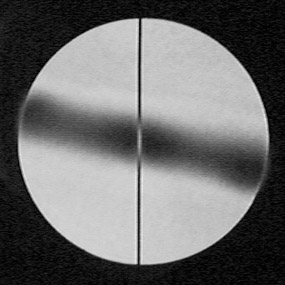
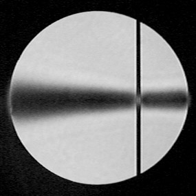
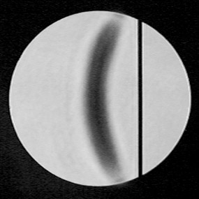
 Now I'll show seven photos of a different setup. I am still using the same 7" f/6 spheroid mirror from the last page, and I am still using the same 0.005" pinhole and blue led for illumination. The push bar on the back is again a solid, horizontal piece of wood. But now the wire pulling on the front of the mirror is offset away from the center. The 150 lpi Ronchi grating detects the presence of the astigmatism. It also shows that the aberration is not symmetrical (left). The next two photos show the situation when a single 0.005" spot is just inside the roc. The photo on the right shows the spot aligned with the short axis of the astigmatism. The bar widens considerably towards the left where the aberration is least. Towards the left this size spot nulls a larger part of the mirror. The bar is narrowest under the vertical wire, where the aberration is greatest. The image on the left shows what happens when the spot is above the center. A curve is clearly seen. I believe each part of this curve has the same roc. |
  |
|
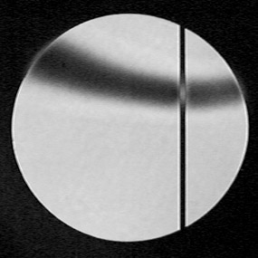
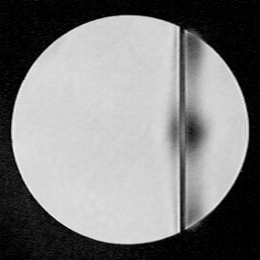
In the pictures below the same spot is just outside the roc. In the left photo the spot is centered in the image of the mirror. The dark bar is strongly curved towards the shadow of the wire. I believe each part of the bar has the same roc. The shape of the bar reflects the shape of the mirror at that point. The image on the right has the spot outside the roc also, but now it has been moved behind the wire. This makes the dark bar straight, indicating that it is now aligned with the long axis of the astigmatism. |
  |
|
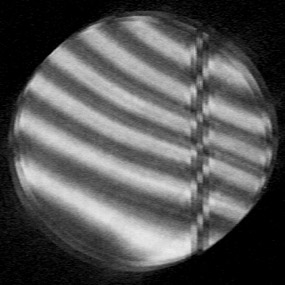
These next two images show my 71 spi Spot Grid well inside the roc. The spots form straight lines where they are aligned with the astigmatism axes. And elsewhere they form curved lines indicating the general shape of the glass. Here is an interesting thing to notice, 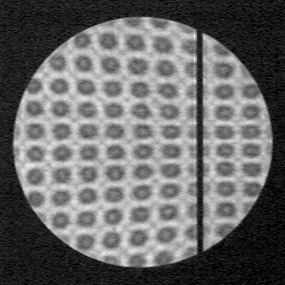 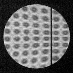 in the image on the left especially. The column of spots directly under the wire is curved to the left, the column of spots to the right of the wire is straight, and the column at the right is curved to the right. in the image on the left especially. The column of spots directly under the wire is curved to the left, the column of spots to the right of the wire is straight, and the column at the right is curved to the right.The shape of the astigmatism imposed upon the spheroid mirror is determined by the wire pulling on the front and the bar pushing on the back, yes, but it is modified by the stiffness of the glass plate being greater towards the left of the wire than towards the right. The same effect is visible in the image on the right, and in the image with a single spot on the right above. From either photo you can learn all of the details available from the previous images. These details can also be learned with the Ronchi grating, but not from one image. To do so you have to rotate the grating to different positions and combine the information learned from each position. |
____________________________________________________________________
____________________________________________________________________
Astigmatism in a paraboloid mirror.
|
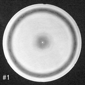
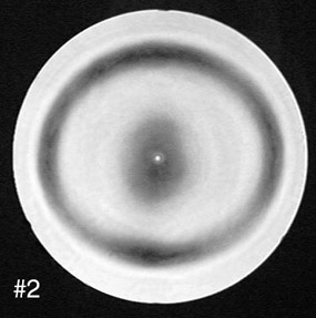
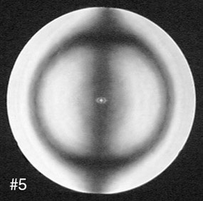
These three photos show increasing amounts of astigmatism on my 22" f/4.5 paraboloid mirror. All of these astigmatism photos use a blue led shining through a 0.005" pinhole for illumination. The dark ring is the part of the mirror with a roc equal to the position of the spot on the optical axis. So the light from that part of the mirror is blocked and it appears dark. For image number 1 this particular zone is round, stigmatic.
If you see any out-of-roundness in the ring it means the zone on your mirror with that radius of curvatu 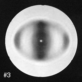 re is not round. For example, it could look elliptical or flower shaped. You could have a situation where the inside zones are astigmatism free but the outside zones show pinching from the cell. Being sure to center the central smudge, the ring could appear round but off-center, meaning another form of astigmatism. re is not round. For example, it could look elliptical or flower shaped. You could have a situation where the inside zones are astigmatism free but the outside zones show pinching from the cell. Being sure to center the central smudge, the ring could appear round but off-center, meaning another form of astigmatism.To measure astigmatism with a notchstick you can measure the horizontal, vertical, and also several diagonal diameters and compare them. Tilt the notchstick and the tester, not the mirror - if you rotate the mirror you will not see any problems caused by heat waves, gravity, or a bad support system. Astigmatism can also be in your eye (as it is in both of mine). It can also be caused by having too much lateral distance between the source and the return. Image 1 has a lateral separation of one inch and astigmatism is negligible. For images 2 through 8 I moved the light source and the image apart laterally (with respect to the optical axis of the mirror) to create astigmatism. Image 2 has a lateral separation of six inches between the light and the spot, and astigmatism is unmistakable. You can plainly see that the darkened zone is not round. Remember that the darkened zone will exactly show the part of the mirror with a roc equal to the position of the spot. You can see and measure the amount of "out-of-roundness" and its orientation (in this case of simple astigmatism the ring is deformed into an ellipse). As near as I can tell, this image shows 5.8 waves of peak-to-valley aberration on the wavefront. Image 3 has a separation of 8.5". Now, imagine using just one line out of your Ronchi grating, and move it up into the roc, you now have the Kent wire test. Into the same astigmatic setup as image 2 above, I now introduce a wire instead of the spot. |
|
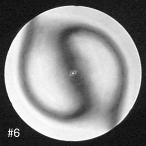
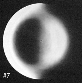
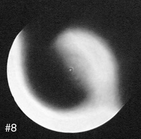
Images 5 through 8 all have 6" of lateral separation, the same as image 2. In image 5 the vertical wire is nearly coincident with the narrow axis of the ellipse of image 2. The astigmatism is nearly undetectable. The ring of the Phi symbol is round, and does not exactly match the zone with the roc of the wire. This image is nearly identical to an image without astigmatism. In image 6 the wire has been turned to an angle between the two different astigmatism axes, and so the Phi symbol has been opened up and now resembles a barred spiral galaxy I once saw. In this orientation the astigmatism is detected by the straight-edge tester. However, it is not apparent from this one image exactly what orientation the astigmatism axes have, how much they differ in length, or much of anything else. The astigmatism is not actually seen, only detected. You would have to test with the straight edge in many different orientations to build up as much information as there is in one spot photo. In the next two photos you can see that the knife edge works the same as the wire. |
copyright ©2002 - 2004 by John Sherman